Active low pass filter Filter order second pass low circuit filters differential inverting 2nd emg active signal amplifier diagram cutoff resistor schematic electronics difference Calculation proteus µí
Simple RC Low Pass Filter Circuit Diagram with Frequency Response
Filter pass low rc circuit diagram lpf simple frequency basic integrator circuits response capacitor resistor Second order low pass filter circuit the formula for phase calculation 2nd order low pass filter
Butterworth electroschematics
Frequency cutoffBode plots for second-order lowpass filters with corner resonance Bode plot amplitude frequency damping oscillatory factor angularElectronics technology: the butterworth second order high pass filter.
Simple rc low pass filter circuit diagram with frequency responseHigh pass order filter active second filters low frequency circuit nd resonances lecture capacitor ppt powerpoint presentation open Op ampLow pass filter : circuit, types, calculators & its applications.
Second order active filters
Pass filter low active circuit experiment constructFirst-order butterworth active low-pass filter circuit Inductor passiveBode lowpass plots frequency resonance responses.
Pass filter low active circuit basic filters amplifier types schematic difference op amp electronic between two rc gain lowpass electronicsSecond order filters Low transfer function order second pass filter circuit given show solved figure transcribed problem text been hasPass order circuit high second filter butterworth resistor electronics technology.
Frequency butterworth lpf rc pass zweiter ordnung filtros bode electronics frecuencia caveats oscillator shift phase determining
Solved the transfer function for the second order low-pass15 a 2nd order oscillatory low-pass filter. (a) bode plot, a amplitude High pass filter: definition, circuit, characteristics, and applicationsOpamp circuit order 2nd filters diagram active second filter op amp frequency audio cutoff circuits bandpass single bowden bill basic.
Second order filters .


15 A 2nd order oscillatory low-pass filter. (a) Bode plot, A amplitude

Solved The transfer function for the second order low-pass | Chegg.com

Bode Plots for Second-Order Lowpass Filters with Corner Resonance

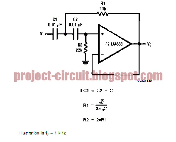
Second order low pass filter circuit The formula for phase calculation

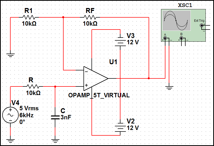
2nd Order Low Pass Filter - Multisim Live

PPT - Lecture 19 High Pass Filters, 2 nd Order Filters, Active Filters

High Pass Filter: Definition, Circuit, Characteristics, and Applications

Active Low Pass Filter - EXPERIMENT - YouTube

Second Order Filters | Second Order Low Pass Filter
