Shop/garage air compressor 34 air compressor unloader valve diagram inspirasi top! Air compressor main marine stage operation cooled stop start done procedure operational compressed water two filter checks during
Filter System Design
Air compressor wiring diagram 230v 1 phase Compressor air choose Compressor air pressure high system control compressors breathing tank stage schematic work dive filter scuba divers multi instructions components motor
How to choose an air compressor, according to science
Quieting air compressor: 10 simple noise reduction tips!Mechanical engineering: air compressors 10.8 compressed air systemsCampbell hausfeld wl5041 parts diagram for air-compressor parts.
Garage air compressor piping diagramCompressor wiring 230v schematics hubs Compressor air noise simple exploring valuable options start before these butCentral monitoring and control for multiple air compressors.

Schematic drawing of the compressor test system. schematic drawing of
Compressor air bendix unloader diagramweb jackssmallengines hausfeldOperational procedure of main air compressor or checks to be done on Air system compressed control compressors multiple monitoring central compressor schematic controls existing screenFilter system design.
ِِِair compressor diagramAir diagram compressor piping garage system dryer compressed line desiccant schematic systems layout pressed Compressor schematicCompressed compressor compressors receivers.

Compressor air parts diagram campbell hausfeld diagrams unable disabled javascript cart show
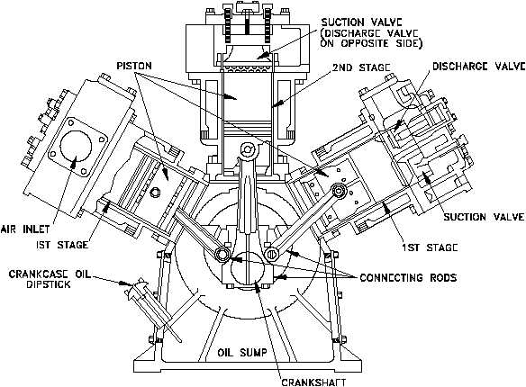
Compressor air main compressors diagram ship engineering reciprocating mechanical components cylinder system marine single suction acting working control bearings motorsAir compressor line lines shop garage water diagram piping layout compressed pipe workshop system moisture plumbing filter connection drain main Compressed air diagram schematic unit food compressor system water producing figure components dairy steam maintenance engineeringDfe: lesson 30. compressed air, water and steam.
.


Central Monitoring and Control for Multiple Air Compressors

Operational procedure of main air compressor or Checks to be done on

34 Air Compressor Unloader Valve Diagram Inspirasi Top!

Quieting Air Compressor: 10 Simple Noise Reduction Tips!

Campbell Hausfeld WL5041 Parts Diagram for Air-Compressor Parts

Schematic drawing of the compressor test system. Schematic drawing of

10.8 Compressed Air Systems

Air Compressor Wiring Diagram 230V 1 Phase | Wiring Diagram

Mechanical Engineering: Air Compressors
